Posts

Showing posts from 2016

Building a MMDVM multi-digital mode repeater

Building a MMDVM multi-digital mode repeater- DRAFT 24/2/2017 Introduction Very draft. Will write more as I go. Everything has arrived and I am starting to put it together. Facebook and Yahoo https://www.facebook.com/MMDVM/ https://groups.yahoo.com/neo/groups/mmdvm How to do everything _Interfacing the CDM 1250 to MMDVM board.pdf in Yahoo files. For 1.01 board and updated files. https://www.f5uii.net/en/installation-calibration-adjustment-tunning-mmdvm-mmdvmhost-raspberry-motorola-gm360/ (Good but had trouble connecting via the network. Will go back to full desktop) DMR-UTAH MMDVM XFCE Raspberry Pi Image  * *        by Chris Andrist, KC7WSU         * * https://github.com/candrist/mmdvm-image * *           kc7wsu@dmr-utah.net    http://digiham.boards.net/thread/13/dmr-repeater Another, includes  CDM1550LS  code plugs https://www.facebook.com/MMDVM/ Posts...
Using notch filters for Rx and TX and extending the range of a notch duplexer

Image
Using notch filters for Rx and TX and extending the range of a notch duplexer (Draft) I have a six cavity notch duplexer for 70 cm. At the original frequencies, outside the amateur band, the RX and TX notch responses are a mirror of the other, as notch filter responses are asymmetrical, compared to symetrical for band pass.. The mirroring of the responses are achieved by adding a quarter wave line to each cavity in the TX half. Being a quarter wave length, it changes with frequency when the duplexer was tuned about 20 MHz lower from its original frequencies. This was enough to stop the mirroring, making the RX and TX curves much the same; high losses for TX. The desired TX shape can be restored by adding about 10 mm to the quarter wave lines on the TX side. The length was calculated as the difference in quater wave between the two TX frequencies, in this case about 8 mm. For this duplexer, it was quite easy as the join to the cavity was soldered. The cable was lengthened by addi...

DVB-T TX Filter: 23 cm filter using 70 cm duplexer

Image
DVB-T TX Filter: 23 cm filter using 70 cm duplexer Introduction I came across a commercial UHF bandpass cavity filter that was as long as a VHF cavity. I removed a coupling to see inside. The probe was nearly 500 mm long, rather than the 170 mm in most UHF filters. They were using the probe as a three quarter length, rather than the typical quarter wave length. I checked the cavity at VHF and, sure enough, there was another peak. The obvious question then was whether the 70 cm duplexer filter would have another bandpass at three times the frequency, about 23 cm? It does! With careful tuning it should be possible to use the ubiquitous 70 cm duplexer at 23 cm. Analysis Raw response With the filter set to 7 MHz at 446.5 MHz, I had scanned three times that frequency and a very wide span. Sure enough, there was a passband, although at a different frequency and three times wider. The frequency of these cavity tuners are determined by a fixed length probe (tube) and a capac...

Duplexer DVB-T TX filter:Technical details (Draft)

Image
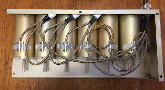
Duplexer DVB-T TX filter: Technical details Introduction Analysis Bandpass is addition of two notches  Three cavities RX to ANT Reverseded notch TX to ANT Sum of two notches with six cavities RX to TX Two left hand couplings are conventional, the two right hand couplings, with plastic spacers are unusual, give reverse notch (not sure how). The image shows internal construction of 4 cavity duplexer. Tuning is achieved by slug into the top of the probes, like a capacitive hat on an antenna. Tubes or probes are slightly less than a quarter wave length. Basically antennas in a box with couplings in and out. Ratio of tube diameter to outside diameter determines impedence. One to three gives about 50 Ohm. SWR of Duplexer filter 7 MHz on 70 cm, not great but probably affected by tuning, possibly by coupling design. Conclusion Coupling for reversed notch needs further investigation

Duplexer DVB-T TX filter: Low bandwidths

Image
Duplexer DVB-T TX filter; Low bandwidths: 2 and 1 MHz. Introduction The duplexer DVB-T TX filter was adjusted to see if it would work at low bandwidths, specifically 2 and 1 MHz at 70 cm. It achieved this easily, but with a small increase in losses. Testing The duplexer was original adjusted for a 7 MHz bandwidth with a spectrum analyser and tracking generator. I only moved the lower frequency notch, one side of the duplexer. At the request of a USA operator, wanting to work DX, I readjusted the filter for a 2 MHz bandwidth. This was possible, with with little effect on losses. For interest, I adjusted it to a 1 MHz bandwidth, again possible, but with slight losses. Discussion The filter works surprising well at the lower bandwidths. I thought losses may have been higher. The losses are not a major issue as the DVB-T amplifier can be driven a little harder to make up for them, and possible even more because of the filter. Notch cavity filters could be ...

Testing a duplexer as a DVB-T TX filter-Wow!

Image
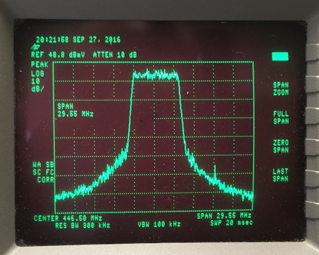
Testing a cheap Chinese duplexer as a 70cm DATV DVB-T 7 MHz TX filter- Wow! Introduction In my last post I described a cheap Chinese duplexer re-tuned as 70 cm DATV DVB-T 7 MHz TX filter. The duplexer uses notch cavity filters, six in all. The notch filters have a much sharper edge, compared to a band-pass filter. The sharp notch seems suited to the vertical edges of a DVB-T signal. I initially check the signal source, a HiDes camera with direct DVB-T output at 1080P. I was a little surprised at the spread, but the filter cleaned it up well. This would indicate the need for a filter before the main power amplifier. I pressed on with just one filter and tried it at the output of the amplifier, a 10 W device, from Darko OE7DBH, using a RA60H4047M1 60 W module. Even with the indifferent input, the filter was able to reduce the spread to -60 dB and give a clean 10 W output. The notch duplexer/filter seems to overcome some of the major hurdles with DVB-T amplifiers and warrants ...

A 70cm DATV TX filter using a cheap Chinese duplexer

Image
A 70cm DATV DVB-T 7 MHz band-pass filter using a cheap Chinese duplexer Introduction DATV transmitters for DVB-T are notorious for "spread" outside the channel, to the point that keeping it 30 dB or more below the signal becomes a limit for power output, typically 10 W out of a 70 W module amplifier. Even with -30 dB spread, it is desirable to have a band-pass filter before further amplification or transmission. Usually an interdigital filter is used, but they are either expensive to buy or a bit difficult to build. VK4JVC suggested using a cavity filter duplexer instead. I tried a four cavity notch duplexer, but the pass-band losses were too high, more than 20 dB. I had bought a cheap, ~A$100, Chinese Jiesai  duplexer, but had put it aside as the response looked bad. After try other duplexers (notch and pass-reject types), I tried the Chinese one again, this time successfully. The result is that the Chinese filter seems to provide a good pass-band for the 7 ...

Airspy, Spectrumspy, noise source and UHF cavity filter characteristics; a low cost spectrum analyzer?

Image
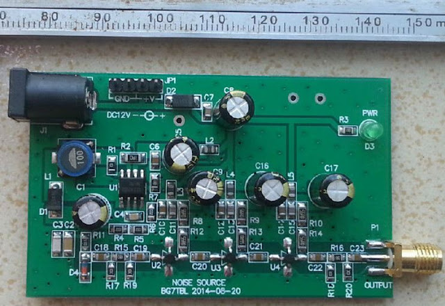
Airspy, SpectrumSpy, noise source and UHF cavity filter characteristics; a low cost spectrum analyzer? Introducton A basic spectrum analyzer/tracking generator for less than $250? Yes. Can it be used to do a demanding task like tuning a UHF cavity filter from a repeater? Seems so. The "proof of concept", spectrum analyzer software, SpectrumSpy, can be used with the Airspy SDR and a noise source to show the characteristics of a pass-reject UHF cavity filter. SpectrumSpy and Airspy SpectrumSpy, "proof of concept", spectrum analyzer software is a new addition to the SDR# download for use with the Airspy SDR. It has the potential for a new direction with low cost SDRs, spectrum analyzers.  Spectrum analyzers are expensive; $1500 then skyward. SpectrumSpy: http://airspy.com/download/ (separate executable in SDR# folder). Airspy has a 24 – 1800 MHz native RX range, but down to DC with the SpyVerter option. http://airspy.com/ $199  and US$59 An earlier post is...

Low cost spectrum analyser/ scanner with AirSpy and RTLSDR

Image
Low cost spectrum analyser/scanner software for the Airspy and RTL-SDR Introduction It is not often I am amazed at new technology, especially for free, but the Spectrum Spy software, a spectrum analyser/scanner for the Airspy SDR, impressed me. It is a poor man's spectrum analyser. However, it is preceded by at least two spectrum scanners for the RTL-SDR hardware; rtl_power and RTLSDR Scanner . This post will compare the two devices and three software packages, scanning the entire FM band and the 100 MHz of the local TV band. The software The three programs all run under Windows, Windows 10 in my case. All three installed and ran without much difficulty. Spectrum Spy is part of the SDR# software package. It is a separate program to SDR#, but in the same folder. Spectrum Spy has a spectrum and a waterfall. It updates every few milliseconds, depending on the span. Spectrum Spy only works with the US$199 Airspy. I have a V1 Airspy. RTLSDR-Scanner is a stand-alone prog...

200W DATV power amplifier- 50V 20A power supply

Image
200W DATV power amplifier- 50V 20A power supply Introduction I am builder a DATV power amplifier, about 200W maximum. The power supply is unusually powerful as the amplifiers are only bout 25 per cent efficient. Commissioning such a power supply is not simple. DATV power amplifier I discovered through one of the Yahoo groups that it was possible to buy UHF DVB-T pallet amplifiers, broad band from 470 MHz to 900 MHz. I bought one through the Italian eBay for 400 Euro. It has a pair of BLF888A  LDMOS transistors. The pallet is a pair of amplifiers with a splitter and combiner to allow single in and out. The BLF888A are each a match pair of transistors in push-pull. Power supply The power requirements are about 48V at 20A as the amplifiers are only about 25 percent with the ultra linear DVB-T. I remembered that a lot of telecommunications equipment use 48V, so had a look on eBay. I managed to buy a new  ELTEK Flatpack2 2000W 48V HE Power Supply...

Three cavity notch RX filter for 2 m with 1.6 MHz RX/TX spacing

Image
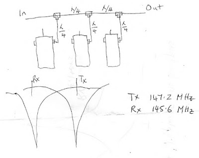
Three cavity notch RX filter for 2 m repeater with 1.6 MHz RX/TX spacing Introduction A three cavity notch filter was constructed and tested. The RX filter has over 80 dB of TX rejection. Construction The club has a 2 m repeater that is to operate on the new 1.6 MHz RX/TX spacing, as opposed to the usual 600 kHz spacing. The existing high/low pass reject cavities could not accommodate the wider spacing, limited to about a 1.1 MHz spacing. The club has five 1968 band pass filters, old but well made. A pair of them had been used with a phasing harness to act as notch filters, but the rejection was not high enough for TX reject on RX. Two are probably adequate for the TX filter to reject spurious noise at the RX frequency. I decided to try and make a three cavity notch RX filter, necessitating a new phasing harness. Each of the cables are a quarter wavelength, with those going to the cavities a little shorter to allow for the probe inside the cavity. I used LMR-400 ultraflex fo...

Duplexer isolation: limits of instrumentation

Image
Duplexer isolation: limits of instrumentation Introduction With high isolation duplexers, about 100 dB, conventional spectrum analysers and tracking generators are beyond their capability of about 80 dB. The rejection of a high isolation duplexer can be checked using a RF signal generator and spectrum analyser. High isolation duplexers. I have a couple of sets of four cavity 70 cm pass reject duplexers. The two cavities give about 70 dB rejection, which is ok but more would be better for RX. A third cavity can be added for greater isolation. Each cavity is individually tuned with a spectrum analyser and tracking generator. The two cavity duplexer can then be assembled and tested. A nice plot with about 70 dB rejection at 438.1 MHz and a pass of 433.1 MHz. Adding the third cavity results in noise at the rejection notch. The spectrum analyser cannot show the full depth of the notch; it does not have enough dynamic range. RF generator and spectrum analyser A RF...

Tuning the receiver front-end of a Kenwood TKR-750 repeater

Image
Tuning the receiver front-end of a Kenwood TKR-750 repeater Introduction I bought a second-hand Kenwood TKR-750-1 VHF repeater. However it was not clear what band the receiver was tuned to. The actual receiver and transmit frequencies can be programmed with a computer. However the the receiver band width is tuned with a spectrum analyser and tracking generator. This post describes how to re-tune the receiver front end. The band pass filters for a 2m repeater RX are quite critical as they are the only selectivity. With a 600 kHz spacing, the cavity filters are usually just isolating the TX and RX when sharing the same antenna, but providing no bandpass to strong nearby signals. Starting point and instrumentation I have an old HP8591A spectrum analyser and tracking generator, circa the 1990s, but still a capable instrument. The basic procedure is to connect the tracking generator output to the RX antenna input and the spectrum analyser input to a test point after the RX bandp...