Posts

Showing posts from 2015

Cavity resonators; size does matter and preview of my HP 8591A spectrum analyzer
Image
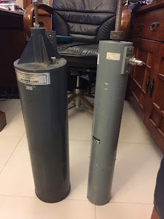
Cavity resonators; size does matter and preview of my HP 8591A spectrum analyzer The Q or quality of a cavity resonator or filter is critical. The simplest way of increasing Q is to increase the diameter. The club has been lent what seemed a pretty ordinary 2 m cavity resonator; even has UHF rather than N connectors and is light. I wasn't expecting too much. But it is 150 mm diameter compared to the 100 mm ex-government cavity filters the club has. The two cavity filters. Note that the filters are not tuned to the same frequency; but they are not too far apart to make a difference to Q. However, what a difference size makes! The Q is visibly much better. Note, none of the instruments were calibrated for this exercise, it is just to show the qualitative difference. First, the quick and dirty antenna analyzer and a 50 Ohm terminator. Then with the club's Rigol spectrum analyzer. Then with my recently acquired HP 8591A spectrum analyzer; 1990s

HP 437B power meter: new toy; traps for beginners

Image
HP 437B power meter: new toy; traps for beginners Introduction and traps for beginners I have recently turned 60 and decided to get some new toys, in the form of stand-alone test equipment. For some odd reason, mainly curiosity, I decided a power meter would be useful, so I bought a 20 year old HP 437B power meter, with sensor and attenuators. Modern power meters of similar capability are about $10K or more! As well as being expensive, the meters are not particularly intuitive to use, primarily because they use a range of power sensors that have very different features, discussed in this post, as it is a trap for beginners. In my case, the sensor was too sensitive for the unit's calibration signal; requiring attenuators just to get the device working. Power measurement is not a simple task, other than for a unmodulated carrier; much less, a 7 MHz wide digital TV signal, especially DVB-T with 8000 carriers across its bandwidth.  Power measurement is not covered well in the l

Problems of different metals in a cavity resonator: Galvanic series

Image
Problems of different metals in a cavity resonator: Galvanic series A problem building a cavity resonator is the potential of electrolytic corrosion between different metals, such as copper and aluminium. This can be overcome by keeping the cavities dry and using a sacrificial anode, such as zinc, already part of the design. The Galvanic series for metals in sea water is shown below. From the table mixing copper and aluminium, is potentially not a good idea. However...   A cavity usually resides in the same room as the repeaters that is usually dry, hence no electrolyte to enable galvanic corrosion. Putting the cavity outside is a different story.   Another sneaky trick is to use a sacrificial anode to protect the other metals. Zinc, in the form of galvanised steel can do this. An integral part of my cavity design is the use of galvanised threaded rod to hold everything in place. A secondary function is the galvanic protection of the device with the sacrificial zinc, i

IDSG101/GK101 10MHz touchscreen Function/Arbitrary Waveform Generator

Image
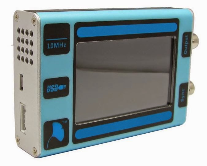
IDSG101/GK101 10MHz touchscreen Function/Arbit rary Waveform Generator Arbitrary waveform capability is compatible with The GK101 10MHz touchscreen Function/Arbitrary Waveform Generator is a indigenous-Chinese designed instrument with significant capabilities at low cost. It is part of the emerging Chinese-designed equipment industry where the design is in-house rather than a copy or licenced design from overseas. Historically, this pattern follows Japan and Korea in indigenous design. China educates more engineers each year as the total number of engineers in the UK, so it is perhaps not surprising. At the moment, there is not a lot of English language support for the GK101. I bought my GK101 for US$99 from InstradStudio, the distributor for the AirSpy SDR (Software-Defined Radio),: http://imall.iteadstudio.com/featured-product/im141013001.html . It is available from eBay at a higher price. There is a wiki for the device: http://wiki.iteadstudio.com/IDSG101 . It provides most

Tuning a commercial UHF duplexer with RigExpert antenna analyser

Image
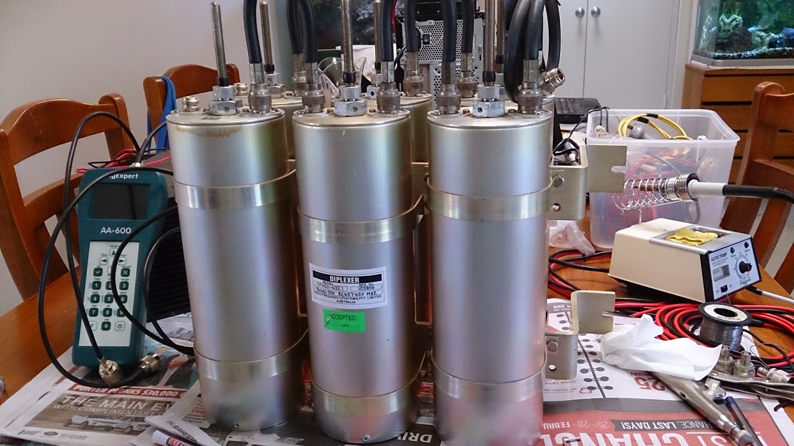
Tuning a commercial UHF duplexer with RigExpert antenna analyser The club is assembling a 70 cm repeater with some equipment kindly loaned to us to use; a Kenwood TKR-820 repeater and a good quality commercial six cavity band-pass duplexer. The tuning was done with a RigExpert antenna analyser that gives a plot of SWR swept across a frequency range. The analyser was able to tune each cavity, but the overall response, while good for separation was compromised, possibly by incorrect inter-connecting cable lengths. Tuning the duplexer The duplexer is a band-pass type, with six cavities, three each for RX and TX with a "T" combiner. The cavities use N connectors and thick LMR400 type cable, and are about twenty years old. The probes are set for maximum coupling, which is desirable for selectivity but for some transmission loss. As a band-pass cavity filter, each cavity has a N connector in and out, making tuning each cavity quite easy; put a 50 Ohm termination on

A $300 2m repeater duplexer and cavity resonators-hardware shop special

Image
A $300 2m repeater duplexer and cavity resonators-hardware shop special Introduction I have been experimenting with cavity resonators for a 2m repeater for some months now. I had been using aluminium tube and brass fittings. However, with 150mm tube, the optimal antenna should be about 50 mm diameter, with a 3:1 ratio of diameters for impedance and performance. However, the mechanical arrangements and conduction between them became problematic. If I wrapped all the joins with aluminium foil, it worked well, but is not practical. In this post I will outline a new technique that uses shim copper (0.1mm) for all the RF parts. The aluminium tube is lined with copper and soldered to copper shim top and bottom plates, in turn attached to the main aluminium plates. The antenna goes back to a conventional fixed lower section, with a movable section to adjust tuning. The basic premise of the design is still that it can be made from readily available parts at low cost, and with basic wo