Posts

Showing posts from 2017

LimeSDR running DATV Express DVB-S TX software

Image
LimeSDR running DATV Express DVB-S TX software (1st draft) With the MiniTioune DVB-S RX, I have begun trying different TX using DATV Express software under Windows 10. The logical first hardware would be the DATV Express hardware TX, but having shifted rooms in the house, I have not been able to find; I know exactly where it was in the other room! The LimeSDR is a popular recent SDR dual duplex transceiver by Lime Microsystems using a new version of their own chip. Cost is about US$250, but they have just announced a mini version for about US$150. It replaces the popular BladeRF; I sold mine to by the new model. DATV Express TX software is available for the LimeSDR; https://discourse.myriadrf.org/t/windows-based-dvb-s-s2-t-transmitter-for-limesdr/1348 (https://wiki.myriadrf.org/LimeSDR-USB) . It worked well without any hitches on 23 cm, with both TX and RX running on the same computer. I am currently using my main PC, but will move it to my fast Dell laptop for project work. Wi

Decontis dtvtools DVB-T/S measurement, analysis and monitoring software

Image
Decontis dtvtools DVB-T/S measurement, analysis and monitoring software (draft)  Introduction There has been a lack of good DVB-T monitoring software for both TX monitoring and RX measurement, unlike DVB-S that has Tutioune. I came across a commercial grade package from decontis that is relative inexpensive and uses a cheap USB-T dongle. While comprehensive, it is not particularly easy to use, but is network-based. I have managed to get it going and plan to use it for TX power amplifier modification and monitoring. My favorite element is a proper constellation chart. Other software and hardware The available DVB-T measurement,   analysis and monitoring  software is limited. CrazyScan2 for terrestrial/cable DVB-tuners https://sourceforge.net/p/crazyscan/wiki/Info/ uses PCTV USB tuner. The other alternative is to use a TV tuner, which gives MER and BER, but not constellation diagrams. A standalone TV installer instrument can be used, but good ones are expensive. Professional equi

MiniTiouner DVB-S receiver build

MiniTiouner DVB-S receiver build (draft) Works well, some fiddly soldering. Gives me DVB-S capability Assembled version coming, about $100 from DATV Express group. Links Unique hardware: https://www.batc.org.uk/shop/minitiouner https://wiki.batc.tv/MiniTiouner_hardware_Version_2 https://wiki.batc.tv/MiniTioune_software https://www.videohelp.com/software/LAV-Filters All codecs: https://www.videohelp.com/software/sections/codec-packs https://wiki.batc.tv/File:Notes_on_building_the_BATC_v2_Minitiouner.pdf

Japanese TRX use JIS not Phillips screws

Image
Japanese TRX use JIS not Phillips screws Ever wonder why it is so easy to damage a screw on a Japanese made radio using a Phillips head screwdriver? Obscure, but simple, they use JIS screws not Phillips! I haven't checked, but I think they are on made-in-Japan cars, certainly lots of other gear. JIS screws, which pre-date Phillips by 20 years, usually have a dot or other indent on the head. The solution is simple, buy a set of JIS screwdrivers, about $25 on eBay. http://themtblab.com/2016/01/tools-vessel-jis-screwdriver.html

RF tap for panadaptor/second SDR after IC-7300 bandpass filters

Image
RF tap for panadaptor/second SDR after IC-7300 bandpass filters (First draft) Introduction It is possible to tap into the IC-7300 after the bandpass filters, just before the ADC. There is a coax connector that allows an SDR tap to receive the filtered RX signal. It is shared with the low-level TX path, but the levels are low, giving a TX monitor too. Using CAT controls, the SDR can be controlled by the TRX. It can also operate as a second RX in the operating band. The RF tap is an alternative to the INRAD RX7300-receive antenna cable, with some advantages and disadvantages. Finding the RF tap In an SDR-based TRX there is no IF tap point, but on the IC-7300, there is a RF tap point after the band pass filter and RF amplifier, where an SDR has the good filtering of the IC-7300, but can access the whole operating band. The RF tap point J1431 is shown in a portion of the RF unit schematic from the service manual. The schematic shows the RX, TX and power paths in green, brown and

Power measurements of DVB-T transmitters

Image
Power measurements of DVB-T transmitters- first draft Introduction I have been puzzled for some time about how power of DVB-T amplifiers were measured relative to other modes. This is an important issue in DATV as DVB-T has been criticized as inefficient compared to DVB-S. It would appear that some of the debate comes down to how the power is measured. Most amateurs use simple diode power meters that do not give an accurate reading for DVB-T. In this post, I outline the theory and practice of measuring DVB-T power correctly with either a thermal power sensor meter or envelope power using a spectrum analyser. It is important that the correct measurements be used otherwise it is comparing apples with oranges. Different power measurements are accepted in amateur radio, vis, CW (peak power, key down) compared to SSB (peak envelope power). I wonder if another measurement unit for digital modes may be more appropriate, such as the data rate to the DC power input and spectrum width,

Commercial DVB-T Amplifiers and filters and implications for DATV

Image
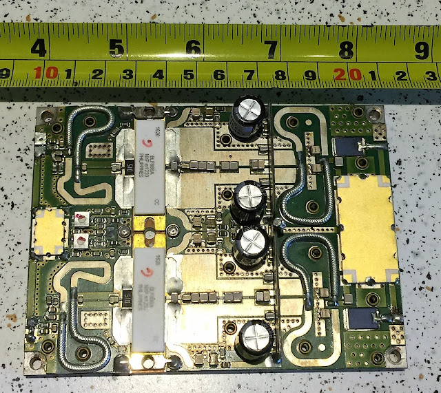
Commercial DVB-T Amplifiers and filters and implications for DATV (first draft) Introduction Commercial solid-state DVB-T amplifiers use about 250 W "pallet" amplifiers; a pair of  amplifiers, each using a pair of LMDOS transistors in a single package. The circuit boards are mounted on a piece of thick copper then on a heat sink. To get higher power, 1 to 50 KW, many pallet amplifiers are used in parallel with a system of splitters and combiners. The amplifier output passes through a series of filters, to stay within a standardized spectrum mask to limit adjacent channel interference. To conclude I note some implications for DATV. Pallet amplifers A typical pallet amplifier is pictured below (bought on eBay). The gold rectangle on the left splits the input to a pair of Doherty amplifiers, while the one on the right combines the amplified signal to the output. The combiner uses a type of circulator to dump RF to a dummy load, the black rectangles on either side of the