Posts

Showing posts from October, 2016

Using notch filters for Rx and TX and extending the range of a notch duplexer

Image
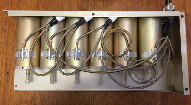
Using notch filters for Rx and TX and extending the range of a notch duplexer (Draft) I have a six cavity notch duplexer for 70 cm. At the original frequencies, outside the amateur band, the RX and TX notch responses are a mirror of the other, as notch filter responses are asymmetrical, compared to symetrical for band pass.. The mirroring of the responses are achieved by adding a quarter wave line to each cavity in the TX half. Being a quarter wave length, it changes with frequency when the duplexer was tuned about 20 MHz lower from its original frequencies. This was enough to stop the mirroring, making the RX and TX curves much the same; high losses for TX. The desired TX shape can be restored by adding about 10 mm to the quarter wave lines on the TX side. The length was calculated as the difference in quater wave between the two TX frequencies, in this case about 8 mm. For this duplexer, it was quite easy as the join to the cavity was soldered. The cable was lengthened by addi

DVB-T TX Filter: 23 cm filter using 70 cm duplexer

Image
DVB-T TX Filter: 23 cm filter using 70 cm duplexer Introduction I came across a commercial UHF bandpass cavity filter that was as long as a VHF cavity. I removed a coupling to see inside. The probe was nearly 500 mm long, rather than the 170 mm in most UHF filters. They were using the probe as a three quarter length, rather than the typical quarter wave length. I checked the cavity at VHF and, sure enough, there was another peak. The obvious question then was whether the 70 cm duplexer filter would have another bandpass at three times the frequency, about 23 cm? It does! With careful tuning it should be possible to use the ubiquitous 70 cm duplexer at 23 cm. Analysis Raw response With the filter set to 7 MHz at 446.5 MHz, I had scanned three times that frequency and a very wide span. Sure enough, there was a passband, although at a different frequency and three times wider. The frequency of these cavity tuners are determined by a fixed length probe (tube) and a capac

Duplexer DVB-T TX filter:Technical details (Draft)

Image
Duplexer DVB-T TX filter: Technical details Introduction Analysis Bandpass is addition of two notches  Three cavities RX to ANT Reverseded notch TX to ANT Sum of two notches with six cavities RX to TX Two left hand couplings are conventional, the two right hand couplings, with plastic spacers are unusual, give reverse notch (not sure how). The image shows internal construction of 4 cavity duplexer. Tuning is achieved by slug into the top of the probes, like a capacitive hat on an antenna. Tubes or probes are slightly less than a quarter wave length. Basically antennas in a box with couplings in and out. Ratio of tube diameter to outside diameter determines impedence. One to three gives about 50 Ohm. SWR of Duplexer filter 7 MHz on 70 cm, not great but probably affected by tuning, possibly by coupling design. Conclusion Coupling for reversed notch needs further investigation