Posts

Showing posts with the label cavity filter

DIY 2m single connector pass reject coupling
Image
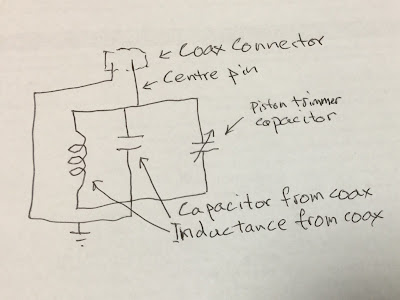
DIY 2m single connector pass-reject coupling Introduction In my last post I describe the repair and tuning of a high performance 2 m duplexer that uses an unusual single connector pass-reject coupling. In this post I describe how to make one for about $30 that achieves the same level of performance. First, I explain what seems to be the theory of the pass-reject coupling as a parallel tuned circuit, using the coax as the inductor and part of the capacitor. The coax conductor is the other part. The variable piston capacitor is in parallel with the coax capacitor to allow tuning. It also gives the necessary mirroring for RX and TX responses. Then I describe how I made one that achieves about the same performance as the original. I am very pleased as I have been working on DIY pass-reject couplers for some time. It allows the construction of a complete high performance, six cavity VHF duplexer for about $300, less the cost of connectors and cabling. Theory of the tuned cou...

2m Duplexer unusual design repair tune pager-reject

Image
2m Duplexer design repair tune pager-reject Introduction My local radio club's main 2m duplexer had an intermittent fault. The duplexer was fixed and retuned to a new channel, 1600, not 600 kHz split, partly to move the RX further from a Pager TX. The Telewave TPRD-1556 Pass-Reject duplexer has an unusual coupler that I had not seen before that works very well, 45 db reject each. They should be possible to DIY. The fault was a defective piston capacitor used to tune a cavity. An unexpected benefit of the pass-reject RX cavities is a significant 72 db reject of the 148 MHz pager TX. More is possible, if needed from notch cavities at 25 db reject each. Tuning high performance cavities, 45 db each, highlights the limitations in instrumentation, particularly the dynamic range, 85 db, with the reject response lost in the noise floor. Design of the Telewave TPRD-1556 Pass-Reject duplexer  The Telewave TPRD-1556 Pass-Reject duplexer looks like any other six cavity pass-r...

Modifying cavity filters for DATV TX or for repeaters

Image
Modifying cavity filters for DATV TX or for repeaters Introduction I am currently doing further work on using notch cavity filters for DATV DVB-T transmitters. My earlier efforts were with what I had at hand and not knowing the solution; I (re)discovered that notch filters clean up DVB-T TX very well. However, it was at low power, 10 W, and high losses, >6 db because of the six cavities in a mobile duplexer. Here, I will report on modifying high power >100 W individual filters. In the next post I will report on using them and determining is just one pair are sufficient. The other goal of this post is to show how easy it is to modify older commercial filters for DATV or repeater use. Modifying cavity filters Old commercial filters are relatively easy to modify as the only thing that changes is the coupling loop, provided they are on frequency (not too hard to change that too!). Notch filters are the simplest as they use a single simple coupling, just a loop of metal. Old co...

Power measurements of DVB-T transmitters

Image
Power measurements of DVB-T transmitters- first draft Introduction I have been puzzled for some time about how power of DVB-T amplifiers were measured relative to other modes. This is an important issue in DATV as DVB-T has been criticized as inefficient compared to DVB-S. It would appear that some of the debate comes down to how the power is measured. Most amateurs use simple diode power meters that do not give an accurate reading for DVB-T. In this post, I outline the theory and practice of measuring DVB-T power correctly with either a thermal power sensor meter or envelope power using a spectrum analyser. It is important that the correct measurements be used otherwise it is comparing apples with oranges. Different power measurements are accepted in amateur radio, vis, CW (peak power, key down) compared to SSB (peak envelope power). I wonder if another measurement unit for digital modes may be more appropriate, such as the data rate to the DC power input and spectrum width, ...

Commercial DVB-T Amplifiers and filters and implications for DATV

Image
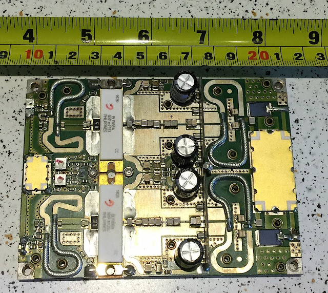
Commercial DVB-T Amplifiers and filters and implications for DATV (first draft) Introduction Commercial solid-state DVB-T amplifiers use about 250 W "pallet" amplifiers; a pair of  amplifiers, each using a pair of LMDOS transistors in a single package. The circuit boards are mounted on a piece of thick copper then on a heat sink. To get higher power, 1 to 50 KW, many pallet amplifiers are used in parallel with a system of splitters and combiners. The amplifier output passes through a series of filters, to stay within a standardized spectrum mask to limit adjacent channel interference. To conclude I note some implications for DATV. Pallet amplifers A typical pallet amplifier is pictured below (bought on eBay). The gold rectangle on the left splits the input to a pair of Doherty amplifiers, while the one on the right combines the amplified signal to the output. The combiner uses a type of circulator to dump RF to a dummy load, the black rectangles on either side of the ...

Using notch filters for Rx and TX and extending the range of a notch duplexer

Image
Using notch filters for Rx and TX and extending the range of a notch duplexer (Draft) I have a six cavity notch duplexer for 70 cm. At the original frequencies, outside the amateur band, the RX and TX notch responses are a mirror of the other, as notch filter responses are asymmetrical, compared to symetrical for band pass.. The mirroring of the responses are achieved by adding a quarter wave line to each cavity in the TX half. Being a quarter wave length, it changes with frequency when the duplexer was tuned about 20 MHz lower from its original frequencies. This was enough to stop the mirroring, making the RX and TX curves much the same; high losses for TX. The desired TX shape can be restored by adding about 10 mm to the quarter wave lines on the TX side. The length was calculated as the difference in quater wave between the two TX frequencies, in this case about 8 mm. For this duplexer, it was quite easy as the join to the cavity was soldered. The cable was lengthened by addi...

DVB-T TX Filter: 23 cm filter using 70 cm duplexer

Image
DVB-T TX Filter: 23 cm filter using 70 cm duplexer Introduction I came across a commercial UHF bandpass cavity filter that was as long as a VHF cavity. I removed a coupling to see inside. The probe was nearly 500 mm long, rather than the 170 mm in most UHF filters. They were using the probe as a three quarter length, rather than the typical quarter wave length. I checked the cavity at VHF and, sure enough, there was another peak. The obvious question then was whether the 70 cm duplexer filter would have another bandpass at three times the frequency, about 23 cm? It does! With careful tuning it should be possible to use the ubiquitous 70 cm duplexer at 23 cm. Analysis Raw response With the filter set to 7 MHz at 446.5 MHz, I had scanned three times that frequency and a very wide span. Sure enough, there was a passband, although at a different frequency and three times wider. The frequency of these cavity tuners are determined by a fixed length probe (tube) and a capac...

Duplexer DVB-T TX filter: Low bandwidths

Image
Duplexer DVB-T TX filter; Low bandwidths: 2 and 1 MHz. Introduction The duplexer DVB-T TX filter was adjusted to see if it would work at low bandwidths, specifically 2 and 1 MHz at 70 cm. It achieved this easily, but with a small increase in losses. Testing The duplexer was original adjusted for a 7 MHz bandwidth with a spectrum analyser and tracking generator. I only moved the lower frequency notch, one side of the duplexer. At the request of a USA operator, wanting to work DX, I readjusted the filter for a 2 MHz bandwidth. This was possible, with with little effect on losses. For interest, I adjusted it to a 1 MHz bandwidth, again possible, but with slight losses. Discussion The filter works surprising well at the lower bandwidths. I thought losses may have been higher. The losses are not a major issue as the DVB-T amplifier can be driven a little harder to make up for them, and possible even more because of the filter. Notch cavity filters could be ...

Airspy, Spectrumspy, noise source and UHF cavity filter characteristics; a low cost spectrum analyzer?

Image
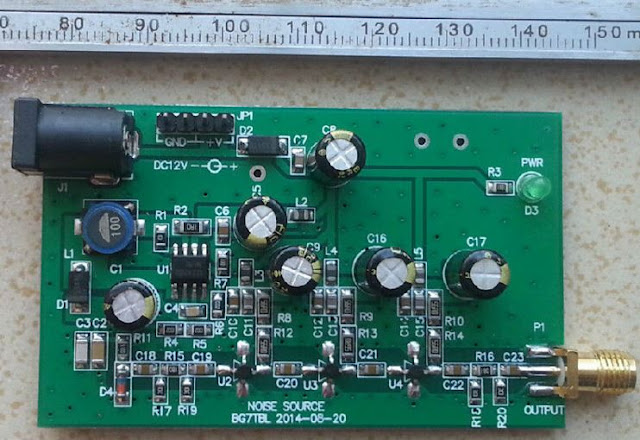
Airspy, SpectrumSpy, noise source and UHF cavity filter characteristics; a low cost spectrum analyzer? Introducton A basic spectrum analyzer/tracking generator for less than $250? Yes. Can it be used to do a demanding task like tuning a UHF cavity filter from a repeater? Seems so. The "proof of concept", spectrum analyzer software, SpectrumSpy, can be used with the Airspy SDR and a noise source to show the characteristics of a pass-reject UHF cavity filter. SpectrumSpy and Airspy SpectrumSpy, "proof of concept", spectrum analyzer software is a new addition to the SDR# download for use with the Airspy SDR. It has the potential for a new direction with low cost SDRs, spectrum analyzers.  Spectrum analyzers are expensive; $1500 then skyward. SpectrumSpy: http://airspy.com/download/ (separate executable in SDR# folder). Airspy has a 24 – 1800 MHz native RX range, but down to DC with the SpyVerter option. http://airspy.com/ $199  and US$59 An earlier post is...

Three cavity notch RX filter for 2 m with 1.6 MHz RX/TX spacing

Image
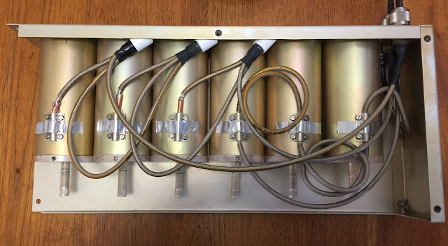
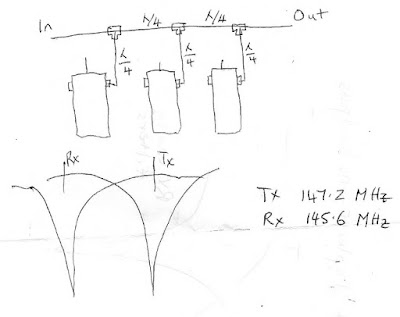
Three cavity notch RX filter for 2 m repeater with 1.6 MHz RX/TX spacing Introduction A three cavity notch filter was constructed and tested. The RX filter has over 80 dB of TX rejection. Construction The club has a 2 m repeater that is to operate on the new 1.6 MHz RX/TX spacing, as opposed to the usual 600 kHz spacing. The existing high/low pass reject cavities could not accommodate the wider spacing, limited to about a 1.1 MHz spacing. The club has five 1968 band pass filters, old but well made. A pair of them had been used with a phasing harness to act as notch filters, but the rejection was not high enough for TX reject on RX. Two are probably adequate for the TX filter to reject spurious noise at the RX frequency. I decided to try and make a three cavity notch RX filter, necessitating a new phasing harness. Each of the cables are a quarter wavelength, with those going to the cavities a little shorter to allow for the probe inside the cavity. I used LMR-400 ultraflex fo...

Duplexer isolation: limits of instrumentation

Image
Duplexer isolation: limits of instrumentation Introduction With high isolation duplexers, about 100 dB, conventional spectrum analysers and tracking generators are beyond their capability of about 80 dB. The rejection of a high isolation duplexer can be checked using a RF signal generator and spectrum analyser. High isolation duplexers. I have a couple of sets of four cavity 70 cm pass reject duplexers. The two cavities give about 70 dB rejection, which is ok but more would be better for RX. A third cavity can be added for greater isolation. Each cavity is individually tuned with a spectrum analyser and tracking generator. The two cavity duplexer can then be assembled and tested. A nice plot with about 70 dB rejection at 438.1 MHz and a pass of 433.1 MHz. Adding the third cavity results in noise at the rejection notch. The spectrum analyser cannot show the full depth of the notch; it does not have enough dynamic range. RF generator and spectrum analyser A RF...