Posts

Showing posts from 2018

Agilent 89640 RF VSA (dc to 2.7 GHz) VXI Vector Signal Analyser

Image
Agilent 89640 RF VSA (dc to 2.7 GHz) VXI Vector Signal Analyser 89640 RF VSA (dc to 2.7 GHz) comprises: E8491B IEEE-1394 PC Link to VXI, C-Size (FireWire) 89605B RF Input and Calibration Module E1439A 95 MSa/s Digitizer with DSP, Memory and 70MHz IF input E2730A 20-2700 MHz RF Tuner E8408A 4-Slot VXI Mainframe 89601A Vector Signal Analysis Software (I have this running but need option 200) https://www.keysight.com/en/pd-1324099-pn-89601A/vector-signal-analysis-software-node-locked-license?cc=US&lc=eng E9285B Modulation Analysis Software https://www.keysight.com/en/pd-1322627-pn-E9285B/modulation-analysis-software?cc=US&lc=eng https://www.finetopix.com/showthread.php/8226-Agilent-E9285B

Vector Signal Analysis: Agilent 89600 VSA software and E4406A Vector Signal Analyser

Vector Signal Analysis: Agilent 89600 VSA software and E4406A Vector Signal Analyser A very powerful test equipment resource is available with the older versions of the Agilent 89600 Vector Signal Analysis software combined with the E4406A Signal Analyser hardware for DATV and other amateur radio. Version 12 of the Agilent 89600 software is the last that will work with the E4406A hardware. It, and earlier versions, can be accessed at: http://www.home.agilent.com/agilent/editorial.jspx?cc=TW&lc=cht&ckey=1303376&nid=-34704.626687.00&id=1303376 or https://www.keysight.com/main/software.jspx?cc=AU&lc=eng&ckey=1303376&nid=-32400.350722.02&id=1303376 The last version of the 89600 software that will work with the Registry edits for version 10 to 12 to work with E4406A https://community.keysight.com/thread/5127 For 89601B versions https://www.keysight.com/main/software.jspx?cc=AU&lc=eng&nid=-32806.0.02&id=2013472&pageMode=PV

Variable-length phasing cables for tuning repeater duplexers: Part 2, Using the cable

Variable-length phasing cables for tuning repeater duplexers: Part 2, Using the cable (draft) Introduction In Part 1, a variable-length phasing cable for use in determining duplexer cable lengths, using M/F SMA connectors to vary the length is discussed. In Part 2, this post, I will cover the use of the variable-length phasing cable in more detail. say more?? The basic process The basic process of using a variable-length phasing cable to tune a six cavity duplexer: 1/ Tune each cavity to frequency. 2/ Connect the three cavities with two same length adjustable phasing cables of approximately the right length 3/ Using a spectrum analyser and tracking generator or a vector network analyser (VNA), take out or insert SMA connectors in both cables until the desired response is achieved. 4/ Using a Tee connector between the ports of the instrument, measure the resonate frequency of one of the correct length variable cables as a quarter wave stub. 5/ Cut a length of cable

Variable-length phasing cables for tuning repeater duplexers: Part 1, Construction of the cable

Image
Variable-length phasing cables for tuning repeater duplexers: Part 1, Construction of the cable Introduction A variable-length phasing cable for use in determining duplexer cable lengths, using M/F SMA connectors to vary the length is proposed. It is a cheaper alternative to a set of phasing cables with a 10mm (5mm?) length increment. This post describes the concept and how it can be replicated. A simple idea, but some frustration in execution. The basic process of using the variable-length cables is outlined. The next post will cover the use of the variable length cables and include screenshots from instruments and photos. The problem: determining cable lengths for inter-connecting duplexer cavities Determining cable lengths for inter-connecting duplexer cavities is a perennial topic. Notionally, they are a quarter wavelength or odd multiple, allowing for coax velocity factor, but in practice that is a starting point. My understanding is that commercially, a set of incr

3D printing or fabricated UHF filters

3D printing or fabricated UHF filters Not crazy idea, being done with antennas. In Jan 2019 QST. Silver conductive paint. Should work for filters. Dimensional stability important with some narrow filters, less so with wideband filters. https://antennatestlab.com/3dprinting https://all3dp.com/1/creality-ender-3-3d-printer-review/ Settings https://www.youtube.com/watch?v=umulfK775i0 https://ultimaker.com/en/products/ultimaker-cura-software https://ultimaker.com/en/resources/50296-which-material-should-i-use Silver coating/paint MG Chemicals Amazon.com https://www.mektronics.com.au/mg-chemicals-super-shieldtm-silver-coated-copper-conductive-coating-ul-recognized-340g.html Fabricated Construct with soldered copper then coat with silver paint. Copper and silver plating https://bryancera.blogspot.com/2014/09/copper-electroplatingforming-3d-prints.html https://www.riogrande.com/category/tools-and-equipment/plating https://janekits.com.au/products/copp

HP AGILENT 8935 E6380A RF TEST SET

HP AGILENT 8935 E6380A RF TEST SET Service Monitor for HF and 2 way radio. They all generate AM, FM and have a calibrated output signal generator, have 2 separate audio tone generators, have 2uV sensitive "off the air receivers" with antenna input, encode/decode standard tone (PL) (CTCSS), have sinad, distortion, S/N meters, receive AM, FM and SSB, have modulation / deviation meter, frequency error meters. Overview and screens for HP 8935 E6380A http://www.amtronix.com/e6380a.htm Comparison with other HP test sets http://www.amtronix.com/diff.htm All manuals available through Keysight, just search E6380.

Commercial low power UHF DVB-T pass-band/notch filter

Image
Commercial  DVB-T pass-band/notch filters: What we can learn Introduction Low power, UHF and VHF DVB-T pass-band/notch filters are commercially available at relatively low cost, ~US$750 that seem suitable for DATV. They seem a good off the shelf solution. By examining such filters, it seems possible to see how they might work, giving some insight into possible home-brew. The filters have two notch filters, one for each side of the signal, as per my earlier posts, to notch the TX skirts. In addition, they have cavity pass-band filters to take out artefacts further out. A manufacturer indicates that the pass filter is a combline, but the mechanical construction suggests cavity filters with openings between cavities for coupling. It seems possible to separate the notch and band-pass filters. For wideband UHF, two notch cavities and a pass-band filter. For 2m, two notch cavities and a single pass cavity may suffice. Low-pass filters are still needed for odd harmonics in addit

450 MHz CDMA duplexer tear down and analysis

Image
450 MHz CDMA duplexer tear down and analysis- draft Introduction Why? I am interested in how modern duplexers work. The club purchased a new 70cm duplexer, only 50 mm tall and not obvious how it worked, but they didn't want me opening it for a look! I purchased a CDMA duplexer from Russia on the 450 MHz band on eBay. It was similar to the 70 cm one. I could get some idea how the UHF one works and some(?!) chance of re-tuning it for either a 70 cm DVB-T TV filter, 7 MHz bandpass, or as a 70 cm narrow pass band repeater duplexer (or both, as there are three chains of seven cavities in the device. Unfortunately, I did not take photos of the duplexer's response before I opened it. However, it was a 6 MHz pass band, with steep skirts, and low pass in the 450 MHz band. I will do it when I put the top back on, but have probably disturbed the tuning. CDMA signals are 1.23 MHz wide, so it is unclear why the pass band is 6 MHz. The outside, with a zillion screws out. The l

Rohde & Schwarz CMU200 Universal Radio Communication Tester resources

Image
Rohde & Schwarz CMU200 Universal Radio Communication Tester resources Introduction This post is a collection of information for the Rohde & Schwarz CMU200 Universal Radio Communication Tester that I have purchased. They can be bought on eBay and other places often for a very reasonable sum. In its day it was an expensive but capable instrument. While the CMU200 is primarily designed for testing now obsolete mobile phone equipment, it can be used for working with analog radio. It has a spectrum analyser, RF generator, RF power measurement and with the option, an audio test set. While not directly having a tracking generator function, there are two PC programs that allow it to be used for testing filters. It can also be done with a noise source or an external tracking generator. The CMU200 uses an embedded Celeron or similar AMD processor running MS-DOS. It has an internal IDE HDD that is wise to replace as the instrument can do tens of thousands of hours. An IDE SSD allo

The Black Art of Duplexers: Demystifying Cavity Filters

Friday 18 May 2018 The Black Art of Duplexers: Demystifying Cavity Filters I prepared a presentation for the Wireless Institute of Australia (WIA) annual general meeting practical day on cavity filters and duplexers. Others may find it useful. Links to the files at the end. "A practical guide to the black art of cavity filters for repeaters and digital TV transmitters. Cavity filters are a mystery to most, but at a practical level, not that hard to make or tune. Drew has developed an inexpensive way of building filters using common materials. There are three basic types of filter, pass-band, pass-reject and notch. It is down to the coupling design, which again can be modified or home built. Each has particular applications. All three can be used in repeater duplexers at VHF and UHF. A Notch filter can be used to block unwanted signals like paging TX. Drew will demonstrate a unique use for notch cavities for cleaning the spurious skirts of DVB-T television power amplifiers and the

Earth Moon Earth communications

Earth Moon Earth communications- very draft Introduction Josh, a new call,  VK4JNA, suggested doing EME. I quickly went from uncertain to keen as it is very similar to satellite tracking, a long term interest. This  post is on EME thoughts, mainly as a record of what we have found; I have a bad memory. It will be updated as we proceed. There will be spin-off posts on things of particular interest. Antenna systems Mast and rotators Locate the antenna at the club; keep partner and neighbours happy. The club has a new tilt-mast for UHF/VHF. Needs to be erected, about $600 to drill hole and concrete. https://www.nbsantennas.com.au/ A priority to get foundation and mount done as the concrete takes a month to cure. The club has a new G-5500 Yaesu EL/AZ rotator. It needs the AL and EZ rotators to be mounted separately to suit the carriage of the mast. The club has a computer rotator controller. https://ea4tx.com/en/tienda/antenna-rotator-system/ars/ I also have the same

Cavity filters for Earth Moon Earth communications

Image
Cavity filters for Earth Moon Earth communications- working draft Introduction Re-inventing wheel? Been done, but not well explained or understood. Google "Cavity filter LNA" or "cavity LNA" https://oz1ct.dk/konstruktioner/144mhz-cavity-lna-mgf1801.html http://www.wa5vjb.com/references/preamp-Cookbook.pdf Good. Impedance matching http://www.ntms.org/eme/presentations/w5lua/WD5AGO_70cm_EME_TCC.pdf AGO design detail http://www.qsl.net/om7aq/lna1.html Cavity filter for EME I haven't seen a cavity filter used in EME, but few know about them. It could be quite desirable to have a pass band cavity filter very close to the antenna and before the broadband low noise amplifier. The LNAs are usually mounted at the antenna, but the loss of a couple of metres of coax (>-0.3 db?) to a cavity filter (>-0.5 db?) may be justified to give 30 db of out of band noise attenuation. This would greatly help in reducing overload of the LNA by such noise. With a

"Plastic Fantastic" Magnetic Loop- Linear actuator drive

Image
"Plastic Fantastic" Magnetic Loop- Linear actuator drive Introduction I have constructed a linear actuator drive version of VK5JST's trombone capacitor tuned "Plastic Fantastic" magnetic loop antenna for 20 m. The linear actuator drive considerably simplifies the construction and waterproofing. The linear actuator was too fast at 10 mm/s. A 12V pulse width modulation (PWM) was used to slow it down to a usable speed. The SWR is dependent on the coupling between the drive loop and the main loop. While 1.1 is meant to be possible, I achieved 1.5 with some adjustment. Tuning the antenna while operating a SDR TRX is possible as the noise is visibly higher in a spectrum scope waterfall; Win4IcomSuite on IC-7300. The noise on the S meter rises from S2 to S6. . The design The antenna uses the underground plastic gas pipe now widely available, including Bunnings. The pipe has a PTFE inner, a layer of aluminium then an outer of yellow plastic. With the PTFE

DIY 2m single connector pass reject coupling

Image
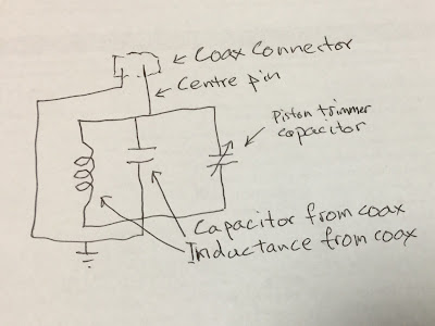
DIY 2m single connector pass-reject coupling Introduction In my last post I describe the repair and tuning of a high performance 2 m duplexer that uses an unusual single connector pass-reject coupling. In this post I describe how to make one for about $30 that achieves the same level of performance. First, I explain what seems to be the theory of the pass-reject coupling as a parallel tuned circuit, using the coax as the inductor and part of the capacitor. The coax conductor is the other part. The variable piston capacitor is in parallel with the coax capacitor to allow tuning. It also gives the necessary mirroring for RX and TX responses. Then I describe how I made one that achieves about the same performance as the original. I am very pleased as I have been working on DIY pass-reject couplers for some time. It allows the construction of a complete high performance, six cavity VHF duplexer for about $300, less the cost of connectors and cabling. Theory of the tuned couplin